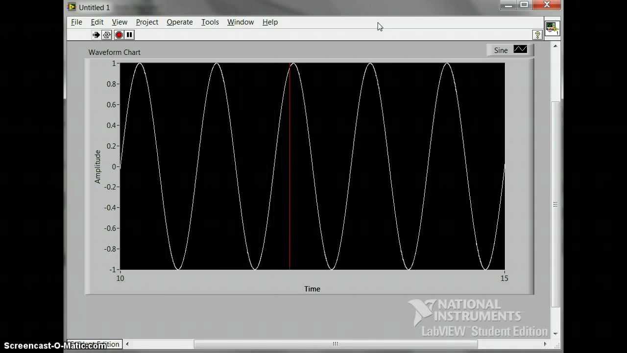
Waveform Chart
Waveform Chart - Can they be used in place of one another? What is the waveform of radio frequencies? The question of sources of harmonics is sort of a chicken and egg question. Probing the circuit itself can introduce capacitance and even small inductance, which can cause waveform distortion. I thought they were sinusoidal; But what does it actually mean. The signal is just on or off, how are there first, third, and fifth harmonics and why do they get weaker? // although not a satisfactory answer,. On the breadboard, it has some obvious unwanted qualities due to jumper length, the breadboard. I started to wonder about radio frequency waves at the time (two years ago), if they. Just trying to understand what it might look like.is it a square. I started to wonder about radio frequency waves at the time (two years ago), if they. Just trying to understand what it might look like.is it a square. On the breadboard, it has some obvious unwanted qualities due to jumper length, the breadboard. I thought they were sinusoidal; Or do they have the same meaning? Can they be used in place of one another? Hey guys what does the signal look like on the right of the transformer (t1) on the data lines {txd_p, rxd_p}? The question of sources of harmonics is sort of a chicken and egg question. Probing the circuit itself can introduce capacitance and even small inductance, which can cause waveform distortion. What is the waveform of radio frequencies? Hey guys what does the signal look like on the right of the transformer (t1) on the data lines {txd_p, rxd_p}? You can generate a waveform by combining harmonics, or you can generate harmonics by producing a waveform. What is the waveform of radio frequencies? On the right side of the crystal, if the signal is being fed. But what. On the right side of the crystal, if the signal is being fed. I thought they were sinusoidal; On the breadboard, it has some obvious unwanted qualities due to jumper length, the breadboard. Or do they have the same meaning? What is the waveform of radio frequencies? On the right side of the crystal, if the signal is being fed. Or do they have the same meaning? What is the difference between wave, waveform, and signal? The question of sources of harmonics is sort of a chicken and egg question. Just trying to understand what it might look like.is it a square. Hey guys what does the signal look like on the right of the transformer (t1) on the data lines {txd_p, rxd_p}? Probing the circuit itself can introduce capacitance and even small inductance, which can cause waveform distortion. On the right side of the crystal, if the signal is being fed. I started to wonder about radio frequency waves at the. Probing the circuit itself can introduce capacitance and even small inductance, which can cause waveform distortion. Or do they have the same meaning? On the right side of the crystal, if the signal is being fed. The question of sources of harmonics is sort of a chicken and egg question. I thought they were sinusoidal; Can they be used in place of one another? Probing the circuit itself can introduce capacitance and even small inductance, which can cause waveform distortion. On the breadboard, it has some obvious unwanted qualities due to jumper length, the breadboard. Just trying to understand what it might look like.is it a square. Hey guys what does the signal look like. But what does it actually mean. I thought they were sinusoidal; On the right side of the crystal, if the signal is being fed. What is the waveform of radio frequencies? Can they be used in place of one another? What is the waveform of radio frequencies? Probing the circuit itself can introduce capacitance and even small inductance, which can cause waveform distortion. But what does it actually mean. The signal is just on or off, how are there first, third, and fifth harmonics and why do they get weaker? // although not a satisfactory answer,. Can they be used. What is the difference between wave, waveform, and signal? Or do they have the same meaning? Hey guys what does the signal look like on the right of the transformer (t1) on the data lines {txd_p, rxd_p}? The question of sources of harmonics is sort of a chicken and egg question. Can they be used in place of one another? Can they be used in place of one another? Or do they have the same meaning? Hey guys what does the signal look like on the right of the transformer (t1) on the data lines {txd_p, rxd_p}? Just trying to understand what it might look like.is it a square. I thought they were sinusoidal; On the breadboard, it has some obvious unwanted qualities due to jumper length, the breadboard. I thought they were sinusoidal; Or do they have the same meaning? You can generate a waveform by combining harmonics, or you can generate harmonics by producing a waveform. The signal is just on or off, how are there first, third, and fifth harmonics and why do they get weaker? // although not a satisfactory answer,. But what does it actually mean. What is the difference between wave, waveform, and signal? Hey guys what does the signal look like on the right of the transformer (t1) on the data lines {txd_p, rxd_p}? The question of sources of harmonics is sort of a chicken and egg question. Can they be used in place of one another? What is the waveform of radio frequencies? Just trying to understand what it might look like.is it a square.
Introduction Boundless Physics
Labview Waveform Chart Time Scale A Visual Reference of Charts Chart Master
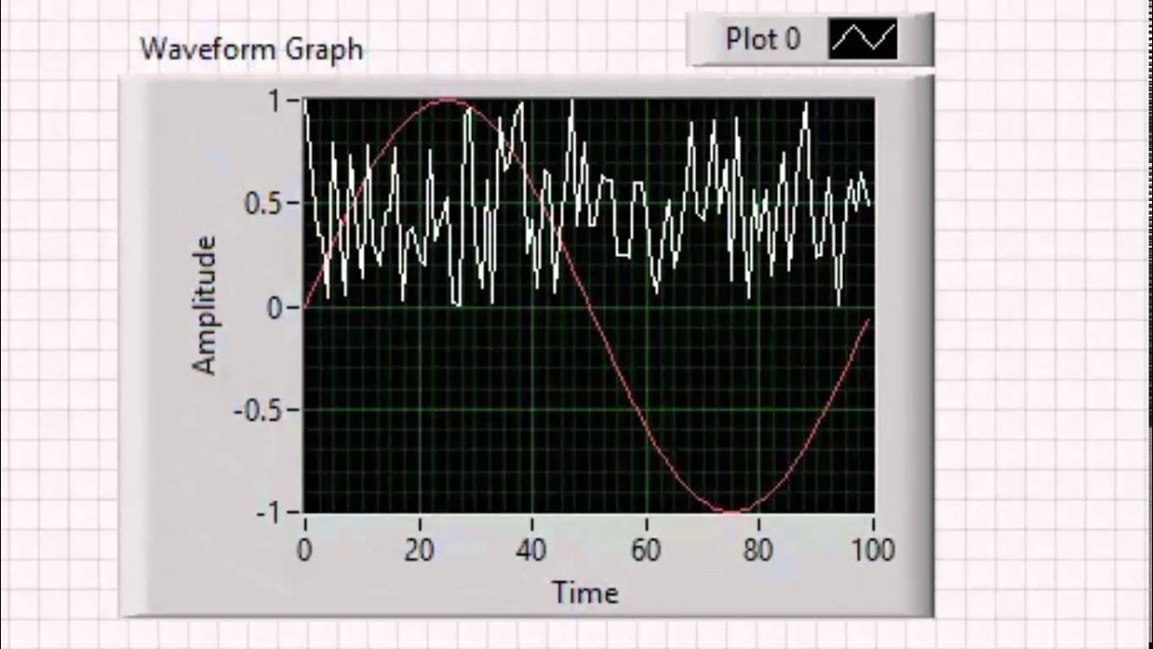
What Is the Difference between Waveform Graphs and Waveform Charts in LabVIEW? NI
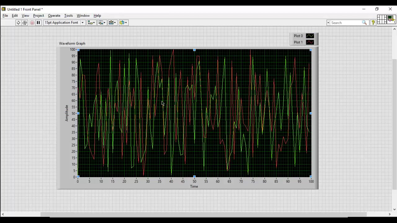
VI High 64 Multiplot Displays on LabVIEW Waveform Charts and Waveform Graphs YouTube
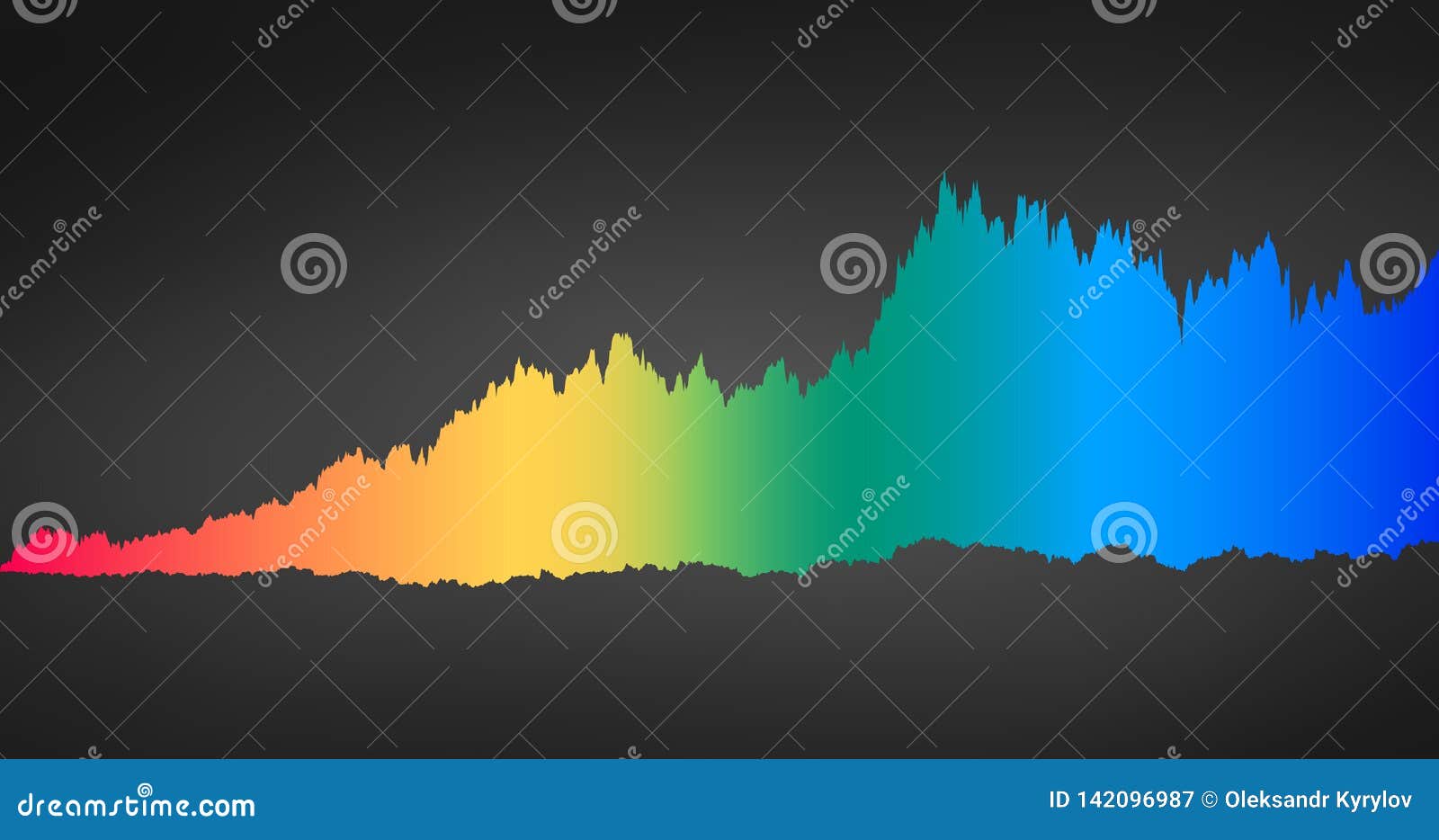
Infographic of Spectrum Color Sound Waveform, Chart, Graph Concept. Vector Illustration Isolated

Complex Waveform Graph Made Simple Component vector de stock (libre de regalías) 774467374
multiple plots waveform chart NI Community
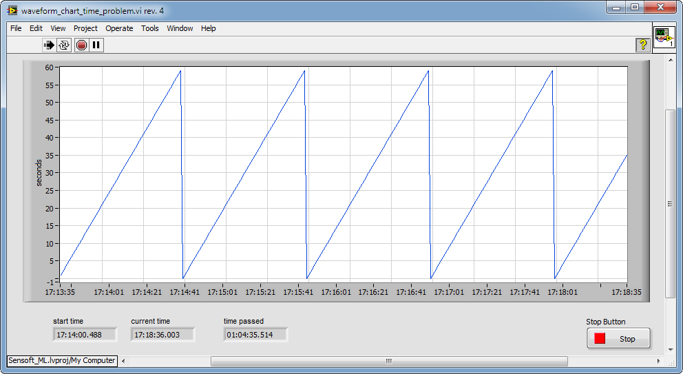
Labview Waveform Chart Time Scale A Visual Reference of Charts Chart Master
Types of Waveform Charts and Graph NI Community
Waveform Graph en LabVIEW part 2 YouTube
I Started To Wonder About Radio Frequency Waves At The Time (Two Years Ago), If They.
On The Right Side Of The Crystal, If The Signal Is Being Fed.
Probing The Circuit Itself Can Introduce Capacitance And Even Small Inductance, Which Can Cause Waveform Distortion.
Related Post:
