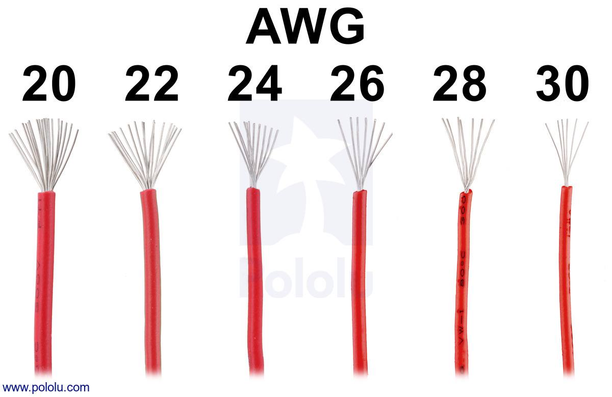
Stranded Wire Awg Chart
Stranded Wire Awg Chart - The maximum resistance values are for the wire as a single conductor. 1/0 1/0 1/0 1/0 1/0 2/0 2/0 2/0 2/0 2/0 3/0 3/0 3/0 3/0 3/0 4/0 4/0 4/0 4/0 4/0 655/36 133/27 259/30 1050/36 133/25 259/27 1666/36 133/23 259/26 665/30 2646/36 133/22. The awg (american wire gauge) wire size chart with detailed specifications on wire diameter, resistance, and ampacity. ** diameter and cross sectional area do not include the insulation. Dimensions and weights are nominal values, subject to standard manufacturing tolerances. This table shows single wire awg on left and equivalent awg when paired, tripled and in quad. The following chart is a guideline of ampacity or copper wire current carrying capacity following the handbook of electronic tables and formulas for american wire gauge. Find conversions between awg sizes and metric units for electrical. Basic stranding configurations are shown to depict some variations in wire awg diameters. *** results may change with real wires: Resistanceweight mil square lbs/ weight ohms/ ohms/ area mm 1000 ft.kg/km 1000 ft. Recommended bunched strands for maximum flexibility recommended ropelay cables for maximum flexibility cabling factor The following awg “american wire gauge” table shows the awg size and diameter in millimeter “mm” and inches in “in”, its cross sectional area in mm2, inche2 and kcmil or mcm and. This table shows single wire awg on left and equivalent awg when paired, tripled and in quad. The following chart is a guideline of ampacity or copper wire current carrying capacity following the handbook of electronic tables and formulas for american wire gauge. Information on this sheet subject to change without notice. *** results may change with real wires: * @ 68°f or 20°c. ** diameter and cross sectional area do not include the insulation. Find conversions between awg sizes and metric units for electrical. Resistanceweight mil square lbs/ weight ohms/ ohms/ area mm 1000 ft.kg/km 1000 ft. Information on this sheet subject to change without notice. * @ 68°f or 20°c. Basic stranding configurations are shown to depict some variations in wire awg diameters. Additional allowances have to be made when the wires are cabled into a multi conductor cable. *** results may change with real wires: ** diameter and cross sectional area do not include the insulation. Dimensions and weights are nominal values, subject to standard manufacturing tolerances. This table shows single wire awg on left and equivalent awg when paired, tripled and in quad. Resistanceweight mil square lbs/ weight ohms/ ohms/ area mm 1000 ft.kg/km 1000 ft. The maximum resistance values are for the wire as a single conductor. Recommended bunched strands for maximum flexibility recommended ropelay cables for maximum flexibility cabling factor * @ 68°f or 20°c. *** results may change with real wires: Resistanceweight mil square lbs/ weight ohms/ ohms/ area mm 1000 ft.kg/km 1000 ft. * @ 68°f or 20°c. Recommended bunched strands for maximum flexibility recommended ropelay cables for maximum flexibility cabling factor Information on this sheet subject to change without notice. The following chart is a guideline of ampacity or copper wire current carrying capacity following the handbook of electronic tables and formulas for american wire gauge. Basic stranding configurations are shown to. The maximum resistance values are for the wire as a single conductor. Resistanceweight mil square lbs/ weight ohms/ ohms/ area mm 1000 ft.kg/km 1000 ft. The following chart is a guideline of ampacity or copper wire current carrying capacity following the handbook of electronic tables and formulas for american wire gauge. ** diameter and cross sectional area do not include. The awg (american wire gauge) wire size chart with detailed specifications on wire diameter, resistance, and ampacity. This table shows single wire awg on left and equivalent awg when paired, tripled and in quad. Recommended bunched strands for maximum flexibility recommended ropelay cables for maximum flexibility cabling factor Find conversions between awg sizes and metric units for electrical. Resistanceweight mil. Basic stranding configurations are shown to depict some variations in wire awg diameters. Recommended bunched strands for maximum flexibility recommended ropelay cables for maximum flexibility cabling factor The following chart is a guideline of ampacity or copper wire current carrying capacity following the handbook of electronic tables and formulas for american wire gauge. The awg (american wire gauge) wire size. *** results may change with real wires: Basic stranding configurations are shown to depict some variations in wire awg diameters. Dimensions and weights are nominal values, subject to standard manufacturing tolerances. The awg (american wire gauge) wire size chart with detailed specifications on wire diameter, resistance, and ampacity. This table shows single wire awg on left and equivalent awg when. The following awg “american wire gauge” table shows the awg size and diameter in millimeter “mm” and inches in “in”, its cross sectional area in mm2, inche2 and kcmil or mcm and. Information on this sheet subject to change without notice. 1/0 1/0 1/0 1/0 1/0 2/0 2/0 2/0 2/0 2/0 3/0 3/0 3/0 3/0 3/0 4/0 4/0 4/0 4/0. Additional allowances have to be made when the wires are cabled into a multi conductor cable. The awg (american wire gauge) wire size chart with detailed specifications on wire diameter, resistance, and ampacity. Information on this sheet subject to change without notice. The following chart is a guideline of ampacity or copper wire current carrying capacity following the handbook of. Recommended bunched strands for maximum flexibility recommended ropelay cables for maximum flexibility cabling factor Additional allowances have to be made when the wires are cabled into a multi conductor cable. 1/0 1/0 1/0 1/0 1/0 2/0 2/0 2/0 2/0 2/0 3/0 3/0 3/0 3/0 3/0 4/0 4/0 4/0 4/0 4/0 655/36 133/27 259/30 1050/36 133/25 259/27 1666/36 133/23 259/26 665/30 2646/36 133/22. American wire gauge (awg) size calculator and chart. The maximum resistance values are for the wire as a single conductor. Basic stranding configurations are shown to depict some variations in wire awg diameters. ** diameter and cross sectional area do not include the insulation. This table shows single wire awg on left and equivalent awg when paired, tripled and in quad. *** results may change with real wires: The following chart is a guideline of ampacity or copper wire current carrying capacity following the handbook of electronic tables and formulas for american wire gauge. * @ 68°f or 20°c. Dimensions and weights are nominal values, subject to standard manufacturing tolerances. Information on this sheet subject to change without notice.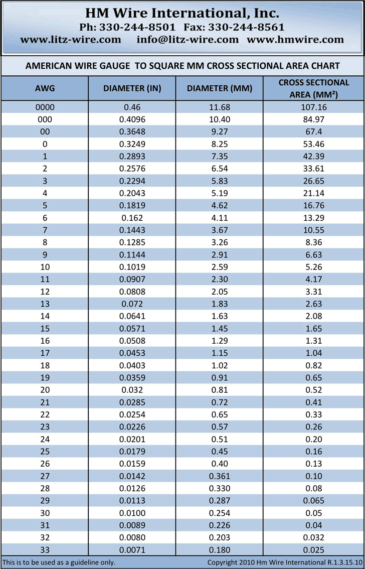
Stranded Wire Gauge Sizes
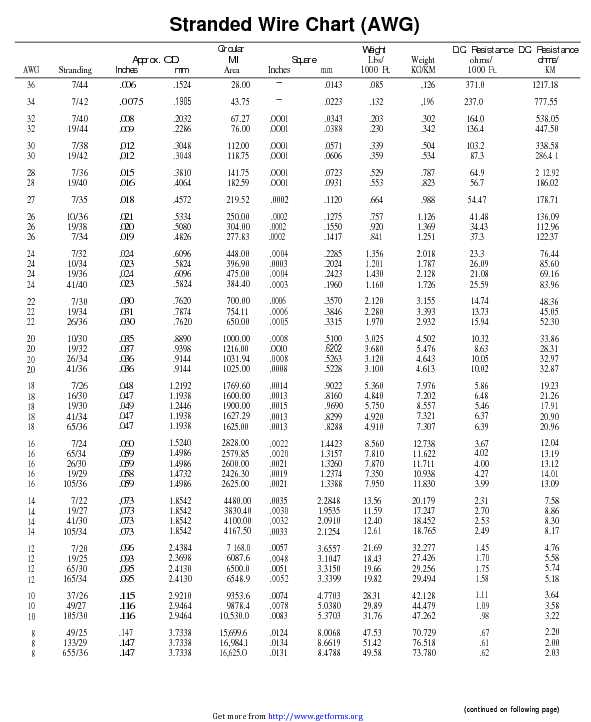
Stranded Wire Chart (AWG) download Size Chart for free PDF or Word
Stranded Wire Gauge Sizes
Stranded Wire Gauge Sizes
Stranded Wire Gauge Sizes

Stranded Wire Gauge Sizes
Awg Stranded Wire Gauge Chart Ponasa
Stranded Wire Gauge Sizes
Stranded Wire Gauge Chart Metric wire to awg chart

Awg Stranded Wire Gauge Chart A Visual Reference of Charts Chart Master
Find Conversions Between Awg Sizes And Metric Units For Electrical.
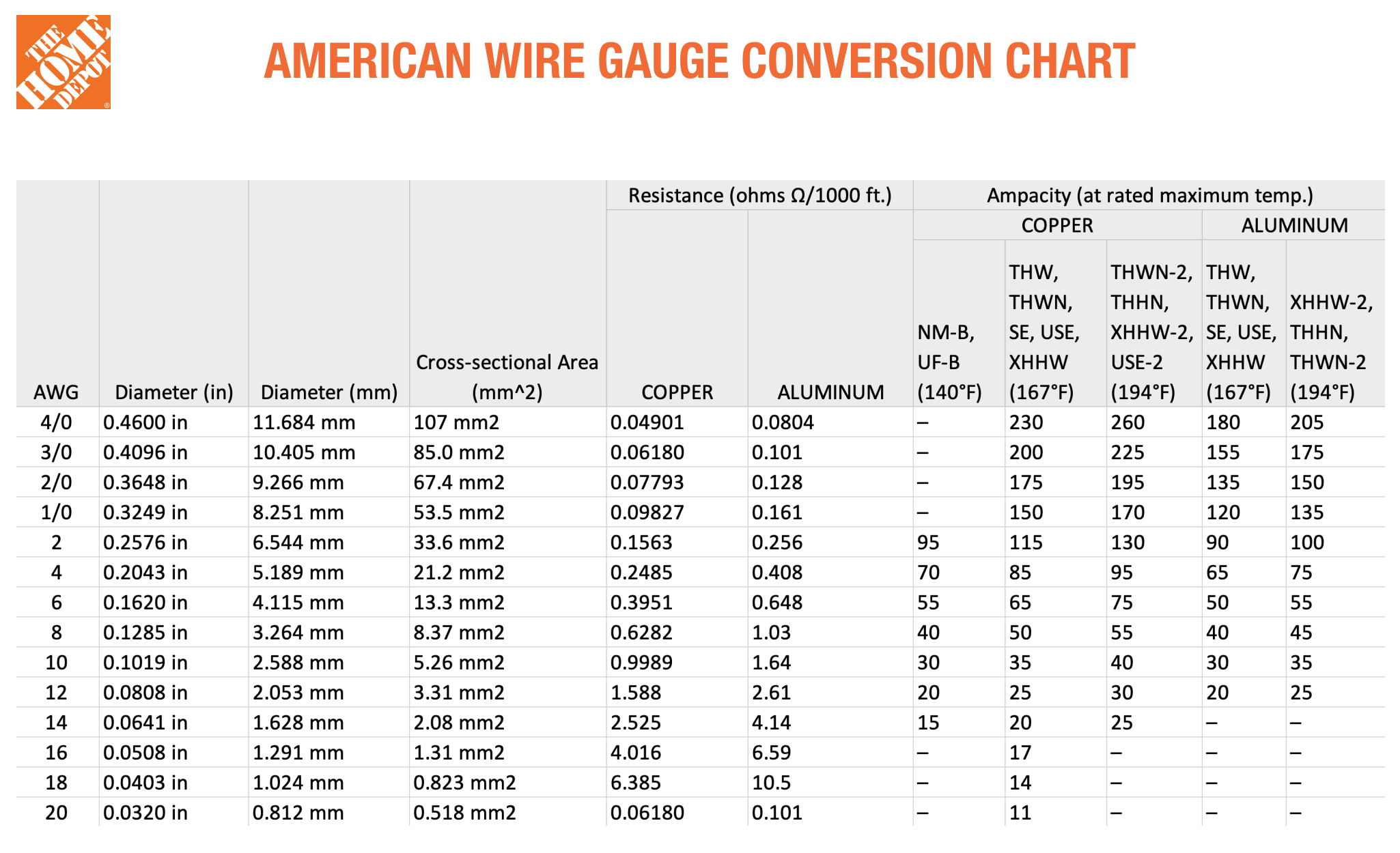
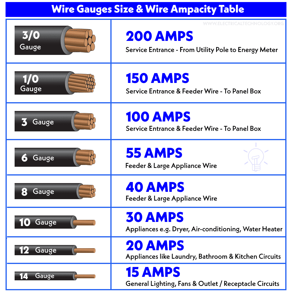
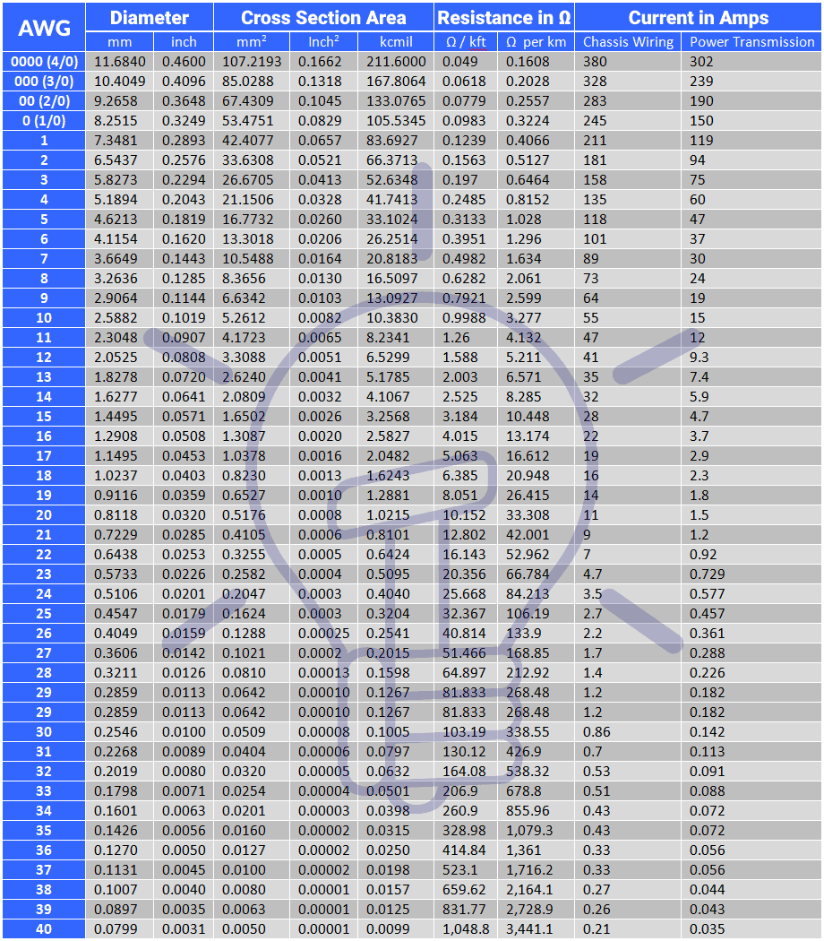
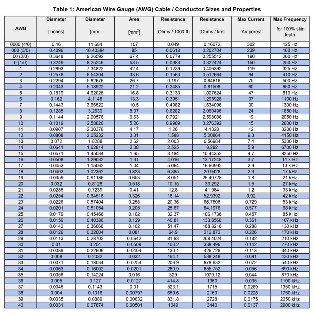
The Awg (American Wire Gauge) Wire Size Chart With Detailed Specifications On Wire Diameter, Resistance, And Ampacity.
The Following Awg “American Wire Gauge” Table Shows The Awg Size And Diameter In Millimeter “Mm” And Inches In “In”, Its Cross Sectional Area In Mm2, Inche2 And Kcmil Or Mcm And.
Resistanceweight Mil Square Lbs/ Weight Ohms/ Ohms/ Area Mm 1000 Ft.kg/Km 1000 Ft.
Related Post: